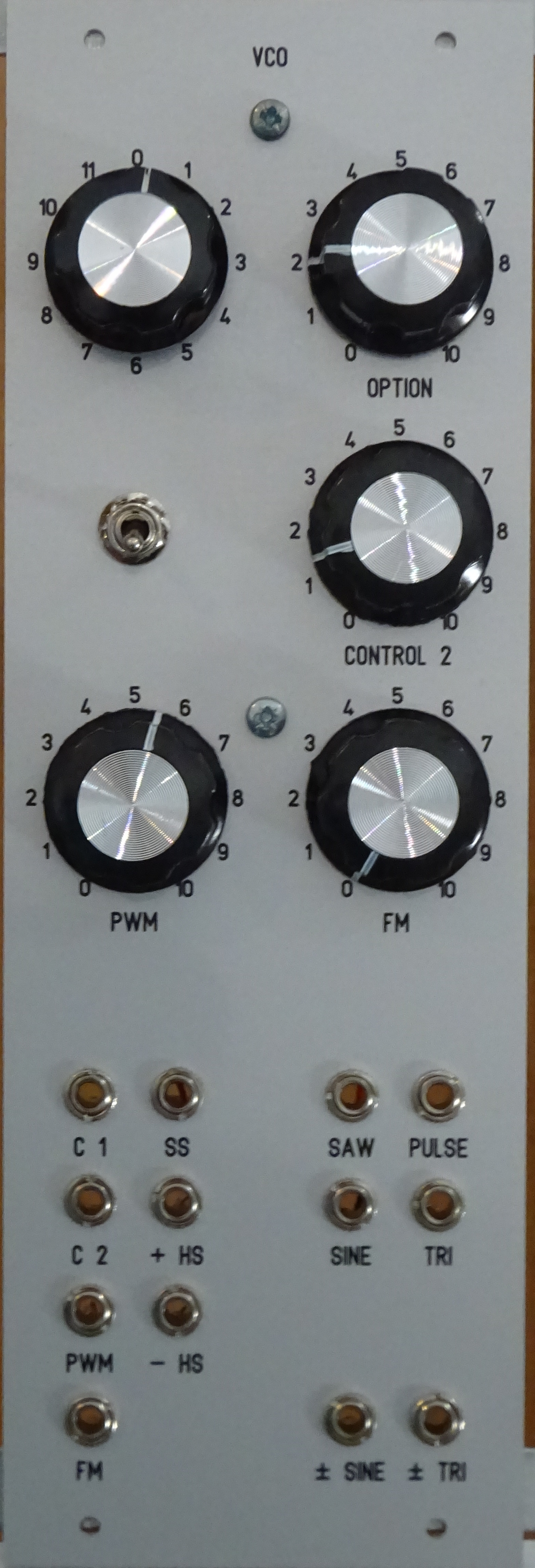
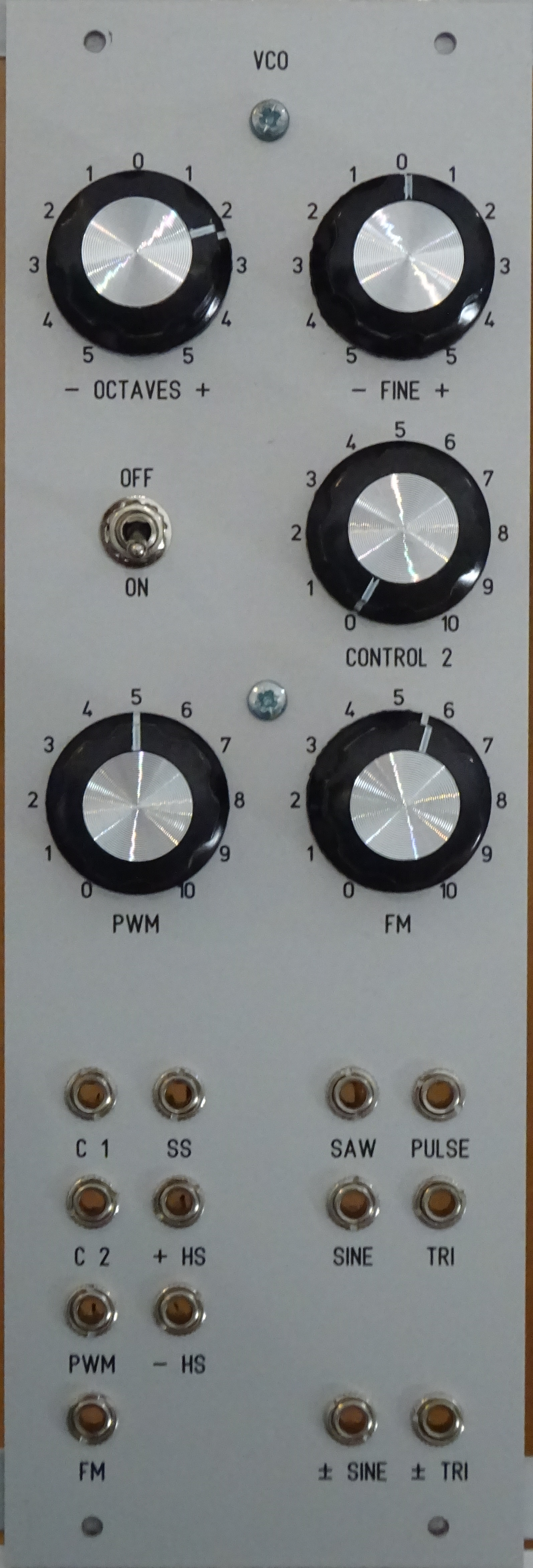
<Back> 24/06/2025

Synthesiser Modules

Social media links: GitHub, Youtube

About

Modules

The Build Process

The Final Product


I made the decision to build the modules on stripboard instead of custom PCBs, but this has lead to the build process taking longer, and the modules construction to be a little sloppy. However practically all modules have had modifications made after the initial construction, which would not have been possible if I was using PCBs. It also costs less to use stripboard. Although, if you plan on building these yourself, I would recommend using proper pcbs and pcb designs.

Nearly all modules have what is called voltage control, which means parameters in the module can be controlled by an external voltage input. This is very common of modular synthesisers and is a core part in how you construct different sounds.

Most of the modules schematic designs are based on the Digisound80, the original documents of which can be found here. The schematic downloads contain both pdfs and the original files. I used KiCad for the schematics, and Front Panel Designer for the panel layouts. The stripboard layouts are the pcb files associated with the schematics. Red tracks are the copper of the stripbarod, Blue tracks are jumper wires, Green is usally a solder bridge and Orange are under or over board jumpers. Some designs use green to mean under and over connections as well, due to overlapping wires.

Most of the stripboard layouts are very cramped, and can be quite difficult to build. This was mostly to save the amount of stripboard I needed as well as the surface area of copper per connection to reduce effects from external noise. As I did not have a geat understanding of electronics at the time I desgined most of these, the filtering capacitors are not in particularly useful locations. Overall I would suggest not using these stripboard layouts if you plan on building some, but downloads are available anyway.

Module list:

VCO

VCO stands for Voltage Controlled Oscillator. It has both pitch and frequency control, and outputs Saw, Triangle, Sine and Pulse waves (with Pulse Width Modulation). There is also Hard and Soft Sync, which allow for the cycle in the oscilation to be reset with an input pulse.

This design is mostly unchanged from the orignal, but some have a multiturn potentiometer for the pitch, and I tweaked how the PWM control functions slightly.

There are 10 of these in the synthesiser.
Downloads: Schematic, Stripboard Layout, Panel Design 1, Panel Design 2

VCLFO

The VCLFO module is the same as the VCO module, but its oscillation range has been shifted to lower frequencies, hence the LF in VCLFO. I added a switch to bring the range back up to VCO levels, so that it can be used as one if needed.

There are 4 of these in the synthesiser.
Downloads: Schematic, Stripboard Layout, Panel Design

VCF

VCF stands for Voltage Controlled Filter. There are 4 types of these in the synthesiser: Low Pass, High Pass, Band Pass, and Phase Shift. Low pass means that high frequencies are taken away, and low ones let through. High pass is the opposite. Band pass is a combination of both low pass and high pass, such that only a band of frequencies around the cutoff is let through, and everything else is taken away. Phase shift means that the effective phase of the oscillation sent through is changed. The phase shift can also be changed into a notch filter, which is the opposite of a band pass.

It has voltage control over both the cutoff frequency and resonance (feedback). I only made slight changes to these designs, so they mostly follow the original. The phase shift however has a few more modifications, adding the notch mode and a self oscillating mode.

There are 2 of each of these in the synthesiser.
Downloads for Low Pass: Schematic, Stripboard Layout, Panel Design
Downloads for High Pass: Schematic, Stripboard Layout, Panel Design
Downloads for Band Pass: Schematic, Stripboard Layout, Panel Design
Downloads for Phase Shift: Schematic, Stripboard Layout, Panel Design

VCSVF

VCSVF stands for Voltage Controlled Stage Variable Filter. This is the same as the VCF module, but it has the option to change its filter function. The original design used the CEM 3335 IC, but there is no replacment for that, so I modified the schematic to use the AS 3330 IC.

There are 2 of these in the synthesiser.
Downloads: Schematic, Stripboard Layout, Panel Design

VCA

VCA stands for Voltage Controlled Amplifier. The volume fo the input signal is changed based upon the control voltage. It is mainly used in conjuction with an Envelope Generator, to turn on and off notes on the instrument.

Each VCA module includes 2 seperate VCA circuits. However to save some space, one VCA module includes 4 circuits within the same panel space, but this makes it quite cramped.

There are 3 + 1 of these in the synthesiser.
Downloads: Schematic, Stripboard Layout, Panel Design
Downloads for larger version: Schematic, Stripboard Layout, Panel Design

VCM

VCM stands for Voltage Controlled Mixer. It has 4 channels, with overall gain and panning. I have not modified the function of this module at all, except for increasing the output gain as I found that it was a little quiet.

There are 2 of these in the synthesiser.
Downloads: Schematic, Stripboard Layout, Panel Design

VCEG

VCEG stands for Voltage Controled Envelope Generator. This module creates the Attack, Decay, Sustain, and Release stages of each note. It is mainly used to as the control voltage input on VCAs or VCFs.

There are 2 of these in the synthesiser.
Downloads: Schematic, Stripboard Layout, Panel Design

MIDI

The MIDI module is one of the only digital modules in the synthesiser, and fully designed by myself. It takes in a MIDI input and outputs 5 channels of CV and gate. There are options to change how the 5 channels are allocated (number of voices and MIDI channels). You can also change how far the pitch bend goes, and octave offsets to the pitch. There are switches to change note priorities when the maximum selected voices has been reached. It also has outputs for velecity and the modulation wheel. When developing the code for this module, I went a bit excessive on the feature set. Because of this it is the only module I made a specific manual for.

There is 1 of these in the synthesiser.
Downloads: Schematic, Stripboard Layout, Panel Design,

Stereo Mixer

The Stereo Mixer module is a 3/6 channel mixer. You can mix either 3 stereo channels, or 6 mono channels. There are indicator LEDs for peaking 10Vpp. This schematic was not part of the original Digisound 80.

There is 1 of these in the synthesiser.
Downloads: Schematic, Stripboard Layout, Panel Design

DRF

DRF stands for Dual Resonance Filter. It is a 2 channel parallel band pass filter that can also mix with the original signal. Each band pass filter has voltage control over the frequency and peak volume. I made some small modifications to the schematic of these. There are also pre-patched connections between the 2 modules to allow for a single Quad channel filter instead.

There are 2 of these in the synthesiser.
Downloads: Schematic, Stripboard Layout, Panel Design 1 Panel Design 2

MFEG

MFEG stands for Multi-Function Envolope Generator. It is very similar to the VCEG, but does not have voltage control over the envolope timings. It contains 2 independent EGs, and the response of the decay and release has 3 selectable modes.

There are 3 of these in the synthesiser.
Downloads: Schematic, Stripboard Layout, Panel Design

Compressor

The Compressor module schematic was designed by Moritz Klein. A compressor suppresses the volume of a signal when it reaches a certain point. I made one change to this design by adding a mixable sidechain signal into the input of the suppressing circuit.

There is 1 of these in the synthesiser.
Downloads: Schematic, Stripboard Layout, Panel Design

RM

RM stands for Ring Modulation. Ring modulation is very similar to amplitude modulation, where the ampltiude of one signal controls the volume of another, however ring modulation also works when the amplitude is negative. It is essentially multiplying the 2 input voltages together to form the output. The design of this module is unchanged, however I added 2 more circuits for a total of 4 isolated multipliers.

There is 1 of these in the synthesiser.
Downloads: Schematic, Stripboard Layout, Panel Design

Wave Folder

A wave folder is a type of saturation, but instad of hard clipping at the peak amplitude, it folds back at the peak voltage line. This circuit contains 2 independent circuits, each with 2 wave folding stages, and gain imbetween then. This is another schematic designed by Moritz Klein. I one main modification by adding the VCA design used in his Compressor modules, to have voltage contrlo over the input gain.

There is 1 of these in the synthesiser.
Downloads: Schematic, Stripboard Layout, Panel Design

Reverb

The reverb module is a spring reverb design by myself. Spring reverb is a reverberation enumation technique that uses coil driven springs to send the signal through. Pickup coils at the other end receive the reverberated signal, which is amplified and mixed with the original to control the amount of reverb. I deceided not to use the reverb design that the original Digisound 80 used, as the ICs would have been especially difficult to source, and I find that spring reverb sounds better that digital simuation. I used a few sources for inspiration and basic designs, including this one by Rod Elliott, and some others.

There is 1 of these in the synthesiser.
Downloads: Schematic, Stripboard Layout, Panel Design

Output

The Output module is more of an IO (Input Output) module, and another one design by myself. It contains a 1W speaker driver for cabinates or headphones, and a stereo line out. The module also contains 2 inputs, that accept line or instrument signals with a gain range of 0.5 to ~∞. The main power switch and indicator LED are also on this panel.

There is 1 of these in the synthesiser.
Downloads: Schematic, Stripboard Layout, Panel Design

Effect

The Effect module is another IO module, but is designed more for a round trip send and receive. It can be used as another dual line in and dual line out, but is has controls to mix in the input with the outgoing signal. This was mainly designed so that I could use guitar effect pedals with the synthesiser.

There is 1 of these in the synthesiser.
Downloads: Schematic, Stripboard Layout, Panel Design

Voltage

The Voltage module is a fixed voltage source. It has 4 seperate outputs, with a rotary switch to select from 0V - 9V outputs. There is then also a control to add an offset ranging 0V - 1V to the base.

There is 1 of these in the synthesiser.
Downloads: Schematic, Stripboard Layout, Panel Design

Op Amp

The Op Amp module is more of a voltage subtractor module. It contains 5 isolated circuits, and a gain control on the output.

There is 1 of these in the synthesiser.
Downloads: Schematic, Stripboard Layout, Panel Design

S&H / Noise

S&H stands for Sample and Hold. Upon every input pulse, the voltage at the signal input is sampled, and remains the output voltage until the next pulse. This module also contains a noise source, which has a white, pink and blue output. The schematic for this follows the original closely, but I added 3 more S&H circuits for a total of 4 within the module. I also moved the clock source circuit to its own module.

There is 1 of these in the synthesiser.
Downloads: Schematic, Stripboard Layout, Panel Design

Clock

The Clock module is 5 clock pulse sources, with individual controllable pulse rates. It is designed to be mainly used as the clock input on the S&H module, but does not have to be.

There is 1 of these in the synthesiser.
Downloads: Schematic, Stripboard Layout, Panel Design

Split

The Split module has no circuit. It is a collection of input jacks that are shorted together in groups. The use of this is to split an output so that it can be sent to multiple locations.

There is 1 of these in the synthesiser.
Downloads: Panel Design

Filter

The Filter module is 5 static, single pole, low pass filters. There is only a control to change the cutoff frequency, so no feedback / resonance. This module was designed mainly to add glide to the keyboard, so would be used in conjuction with the MIDI module and VCO modules. However it can be used as a normal audio low pass filter if nessassary.

There is 1 of these in the synthesiser.
Downloads: Schematic, Stripboard Layout, Panel Design

Quad LFO

The Quad LFO module contains 4 Low Frequency Oscillators. It has a rate control and wave shape selection. This has not been modified from the original design.

There is 1 of these in the synthesiser.
Downloads: Schematic, Stripboard Layout, Panel Design

Mix

The Mix module is 5, 4 channel mixers with an output volume control. There is no individual signal volume control, as the module is mainly to be used as a voltage adder and signal attenuator.

There is 1 of these in the synthesiser.
Downloads: Schematic, Stripboard Layout, Panel Design